• Figure 1
    Figure 1

    Archival photograph of the ornamental engine-turning lathe in the basalt room at the Wedgwood Etruria factory, 1941. Left to right: Mrs. Warrilow, Tom Simpson, and Mary Thornton. (Courtesy, The Warrilow Collection, Keele University Library, Newcastle-under-Lyme, Staffordshire.) In the 1950s this nineteenth-century lathe was moved to the Wedgwood Museum in Barlaston, where it is today. This photograph shows the lathe essentially as it was built; later it was highly modified.

  • Figure 2
    Figure 2

    Coffee pot and cover, England, ca. 1800. Black basalt. H. 9 1/8". The engine-turned surface of this coffee pot and cover was created with the edge (rose) cam. (All objects from the Jonathan Rickard Collection unless otherwise noted; photo, Gavin Ashworth.)

  • Figure 3
    Figure 3

    Detail of the coffee pot illustrated in fig. 2.

  • Figure 4
    Figure 4

    Jug, England, ca. 1775. Red stoneware. H. 7 1/2". (Photo, Jack McConnell.) The engine-turned surface of this baluster-form jug with press-molded masque snip or pouring lip was created with the end (crown) cam.

  • Figure 5
    Figure 5

    Plate, Staffordshire, ca. 1775. D. 8 3/8". (Photo, Jack McConnell.) This rare green-glazed engine-turned plate was worked on the edge cam. Wasters of engine-turned plates were among the finds at the William Greatbatch factory site in Fenton, Staffordshire.

  • Figure 6
    Figure 6

    Mug, England, ca. 1800. Lead-glazed creamware. H. 3 1/2". (Photo, Jack McConnell.) The decoration at the rim of this mug with extruded strap handle with foliate terminals is rouletted and slip-filled, above a reeded band colored in the glaze with either antimony or uranium to produce the brilliant translucent yellow. The two ochre slip bands bracket a field of horizontal black slip bands cut through vertically using the edge cam.

  • Figure 7
    Figure 7

    Jug, England, ca. 1790. Lead-glazed pearlware. H. 7". (Photo, Gavin Ashworth.) Baluster-form jug with slip banding, green-glazed (copper oxide brushed into the lead glaze) reeded bands brushed with a concentrated glaze mixture containing copper oxide, and black slip-filled engine-turned pattern cut using the end cam.

  • Figure 8
    Figure 8

    Detail of the engine-turned pattern on the jug illustrated in fig. 7

  • Figure 9
    Figure 9

    Mug, attributed to the Leeds Pottery, Yorkshire, ca. 1790. Pearlware. H. 6". (Photo, Gavin Ashworth.) Quart-capacity mug with slip banding and a black slip-filled pattern cut with the edge cam. The pattern appears in watercolor drawings in the Leeds Pottery pattern books in the Print Room of the Victoria and Albert Museum.

  • Figure 10
    Figure 10

    Detail of the engine-turned pattern on the mug illustrated in fig. 9.

  • Figure 11
    Figure 11

    A page from the Leeds Pottery Pattern Book No. 3 showing a variety of engine-turned designs. (© V&A Images/Victoria and Albert Museum, London, www.vam.ac.uk.)

  • Figure 12
    Figure 12

    Mug, England, ca. 1800. Pearlware. H. 5 7/8". (Photo, Gavin Ashworth.) Quart-capacity mug, slip-banded with red slip-filled engine-turned decoration cut with the end cam.

  • Figure 13
    Figure 13

    Detail of the engine-turned pattern on the mug illustrated in fig. 12. The mug is shown at an angle, illustrating the trompe l’oeil effect of a faceted surface.

  • Figure 14
    Figure 14

    Mug, England, ca. 1830. Pearlware. H. 4 5/8". (Photo, Gavin Ashworth.) A pint-capacity mug with slip banding and a green-glazed reeded band with a black slip-filled engine-turned pattern cut with the end cam. Wasters of vessels with similar patterns were found in an accumulation from the James and Ralph Clews manufactory, Cobridge, Staffordshire, 1818–1834.

  • Figure 15
    Figure 15

    Detail of the engine-turned pattern on the mug illustrated in fig. 14.

  • Figure 16
    Figure 16

    Cream jug and cover, Leeds Pottery, Yorkshire, ca. 1790. Creamware. H. 5 1/2". (Photo, Gavin Ashworth.) The engine-turned decoration cut through the slip field with a matched set of checkering cams. The extruded strap handle has foliate terminals, and the cover knop is missing. This object was found in Russia. Impressed on the bottom is “leeds pottery.” A related teapot and cover with the same mark are in the collection of the Victoria and Albert Museum.

  • Figure 17
    Figure 17

    Detail of the engine-turned pattern on the jug illustrated in fig. 16.

  • Figure 18
    Figure 18

    Cream jug, Wedgwood, Staffordshire, ca. 1820. Red stoneware. H. 3 1/4". (Photo, Gavin Ashworth.) The engine-turned basketweave pattern of this cream jug with glazed interior was cut using a double-edge cam. It has the impress “wedgwood” on the bottom.

  • Figure 19
    Figure 19

    Detail of the engine-turned pattern on the cream jug illustrated in fig. 18.

  • Figure 20
    Figure 20

    Potpourri basket, Wedgwood, Staffordshire, ca. 1810. Caneware. H. 5". (Photo, Gavin Ashworth.) The caneware body has the same engine-turned pattern as the redware creamware jug illustrated in figs. 18, 19.

  • Figure 21
    Figure 21

    Detail of the engine-turned pattern on the basket illustrated in fig. 20.

  • Figure 22
    Figure 22

    Mug, England, ca. 1800. Pearlware. H. 3 3/4". (Photo, Gavin Ashworth.) A half-pint-capacity mug, slip-banded and cut using a standard edge cam used for vertical reeding, but with a curved blade.

  • Figure 23
    Figure 23

    Detail of the engine-turned pattern on the mug illustrated in fig. 22.

  • Figure 24
    Figure 24

    Mug, attributed to Wood & Caldwell, Burslem, Staffordshire, 1797–1818. Pearlware. H. 3 3/4". (Photo, Gavin Ashworth.) A half-pint-capacity mug, slip-banded with vertical cuts through the slip using the edge cam.

  • Figure 25
    Figure 25

    Detail of the engine-turned pattern on the mug illustrated in fig. 24.

  • Figure 26
    Figure 26

    Jug, Britain, maker unknown, ca. 1830. H. 4". (Photo, Gavin Ashworth.) A green-glazed cream jug with both rouletted and engine-turned patterns decorating the surface. Vestiges of overglaze gilding remain.

  • Figure 27
    Figure 27

    Detail of the engine-turned pattern on the jug illustrated in fig. 26.

  • Figure 28
    Figure 28

    Teapot and cover, England, ca. 1790. Lead-glazed red earthenware. H. 4". (Photo, Gavin Ashworth.) The spout and vertical sides of the body were cut with the end cam, whereas the cover and the pot’s shoulder patterns required the edge cam.

  • Figure 29
    Figure 29

    Detail of the engine-turned pattern on the teapot illustrated in fig. 28.

  • Figure 30
    Figure 30

    Teapot and cover, Davenport, Longport, Staffordshire, ca. 1810. Caneware. H. 4 1/2". (Photo, Gavin Ashworth.) Enamel decorated with engine-turned dicing on the body and cover, this example has the impressed mark “davenport” on the bottom.

  • Figure 31
    Figure 31

    Detail of the engine-turned pattern on the teapot illustrated in fig. 30.

  • Figure 32
    Figure 32

    Jug, Britain, ca. 1820. Pearlware. H. 7 1/2". (Photo, Gavin Ashworth.) A barrel-form jug banded with black and ochre-colored slip, engine turned with the edge cam through the slip to reveal the white body. Green-glazed rouletted bands bracket the engine-turned surface cut with two different blades, the chevron pattern requiring a V-shaped blade.

  • Figure 33
    Figure 33

    Detail of the engine-turned pattern on the jug illustrated in fig. 32.

  • Figure 34
    Figure 34

    A line engraving that depicts a simple dicing lathe, reproduced in Ernest Albert Sandeman, Notes on the Manufacture of Earthenware (London: H. Virtue and Company, 1901).

  • Figure 35
    Figure 35

    Side view of the Carpentier engine lathe showing the basic working components.  (a) The crown (end) cam: left and right edges can be cut with patterns.  (b) Double-action, crown-cam spring assembly: allows crown cam to be followed on left or right edge and creates spring tension for the sideways pumping action. Josiah Wedgwood describes making this addition to his redesigned lathe in a 1768 letter.  (c) Crown-cam follower.  (d) Lock to keep main shaft from moving sideways.  (e) Main springs: put pressure against pivoting main frame as it follows the edge cams and produces a rocking motion.  (f) Wooden pulleys: using a large pulley slows the motion and using a small pulley increases it.  (g) Mainframe locking arm (seen in the down position): prevents the front-to-rear rocking action.  (h) Spring tensioner: increases pressure on main springs, either forward or backward.  (i) Edge cams: can be changed simply by removing a nut and sliding another cam on or off. Like the double-action, crown-cam spring assembly, this appears to have been invented by Wedgwood for use on his 1768 redesigned lathe.  (j) Depth stop: controls the depth of cut the knives make in the body. (All demonstration photos by Gavin Ashworth.)

  • Figure 36
    Figure 36

    The end cam on Carpentier’s lathe. At the lower left is the follower. At right is a portion of the wooden flywheel.

  • Figure 37
    Figure 37

    The edge cam on Carpentier’s lathe. At lower left center is the follower; the flywheel appears in the background.

  • Figure 38
    Figure 38

    Detail of the follower mounted against one of two attached edge cams used, in this configuration, to create checkered patterns. For this application, alternating patterns are cut with one of the edge cams, then the offset patterns are cut with the other.

  • Figure 39
    Figure 39

    Another view of the follower and an edge cam. The follower’s size can be changed depending on the size and intricacy of the pattern needed to be run against on the edge cam.

  • Figure 40
    Figure 40

    Don Carpentier at his lathe. Left to right: a leather-hard pot mounted on a plaster chum, or mandrel; the edge cam; clamp; and the wooden flywheel.

  • Figure 41
    Figure 41

    To illustrate the pantographic effect of the cam in relation to the pattern cut on a pot, Don devised this arrangement of an edge cam with a period mug. The white lines on the cam show the reduction of the edge pattern to the final cut. The larger the cam, the more spread out the pattern became, thus increasing the ease of following the pattern. (Collection of Donald Carpentier.)

  • Figure 42
    Figure 42

    An assortment of end and edge cams, each of which is capable of many patterns depending on the blades chosen.

  • Figure 43
    Figure 43

    An assortment of cutting blades.

  • Figure 44
    Figure 44

    A group of engine-turned vessels having a variety of decorations. (Collection of Donald Carpentier; photo, Gavin Ashworth.) All of these pieces were cut using one or both sides of a checking cam, similar to the one seen in the center of the illustration. Most of the variations were created by changing either the slip colors or the patterns on the ends of the cutting blades.

  • Figure 45
    Figure 45

    Beginning the process of cutting a pattern into a quart-mug’s surface using the end cam. The pot revolves as the blade gradually begins to cut into the surface.

  • Figure 46
    Figure 46

    With the pattern completely cut in, the surface is flooded with colored slip and set aside to dry.

  • Figure 47
    Figure 47

    After drying, the excess slip is turned away with a flat blade, exposing both the white body of the pot and the red clay inlay.

  • Figure 48
    Figure 48

    Detail of the inlaid slip pattern prior to the biscuit firing.

  • Figure 49
    Figure 49

    The completed mug prior to biscuit firing. As these modern pots are intended to be used, non-leaded glazes are applied. Carpentier discovered that lead was an integral component in producing the colors of the glazes. Consequently, he had to develop his own clay sources and color recipes to achieve the look of the original lead-glazed products.

  • Figure 50
    Figure 50

    Jug, British, ca. 1820. Pearlware. H. 7 3/4". (Collection of Donald Carpentier; photo, Gavin Ashworth.) A barrel-form jug, slip-banded with black slip-filled rouletted decoration. Rouletted decoration such as this illustrates the imprecise geometric patterns achieved by hand, as opposed to the regular patterns found on engine-turned wares. The use of the end cam seems to have diminished by the 1830s, but edge-cam work continued to the end of the nineteenth century. By the early nineteenth century the much simpler and less expensive dicing lathes were available as stock items. Cams were also available in standard sets, obvious from sherds found on various factory sites. The only known period engine-lathe cams are at the Wedgwood factory in Barlaston, Staffordshire.

  • Figure 51
    Figure 51

    Detail of a rouletted inlay in three different patterns, together with a rouletting wheel in one of those patterns (three different roulettes were used). Many factories were too small or too under-capitalized to afford even a dicing lathe, and they had few options available in order to compete. One of those options was to become very creative with the practice of inlaid rouletting. Most factories had a variety of these inexpensive and easily available patterned wheels that could be used in a variety of combinations. The surface of the pot was simply embossed using the roulette and the ornamental depression created was filled with a colored slip. Once the slip had set, the excess was trimmed away on the lathe, leaving an inlaid pattern. Many inlaid designs are similar in design to engine-turned patterns and are incorrectly attributed to engine turning by many dealers and collectors.

  • Figure 52
    Figure 52

    Teapot, Staffordshire, ca. 1770. Earthenware. H. 4 1/8". (Courtesy, Skinner’s.) This teapot has typical engine-turned decoration under its colorful glaze, and without close inspection one would assume that it had been cut on such a lathe. In fact, this pot was press-molded. The blocks used to produce the molds in which it was pressed were made from an original master model that was, in fact, cut on an engine lathe. Mold marks run down both the front and rear of the pot and are partially obscured by the handle and spout. This technique was one of the ways that small potteries could compete with larger firms that had expensive engine lathes.

  • Figure 53
    Figure 53

    Beginning the process of cutting a pattern with the edge cam through firm slip on the leather-hard body of a quart mug. Because of the need for full circumferential access, the last step before biscuit firing is the application of the 
    handle. In this pattern, chevrons are an integral part of the design, so a V-shaped rather than flat blade is used. The rouletted patterns near the rim and the foot will be brushed with a concentrated glaze mixture containing copper oxide

  • Figure 54
    Figure 54

    The earliest stage of cutting the chevron pattern.

  • Figure 55
    Figure 55

    The pattern begins to reveal the body color beneath the slip.

  • Figure 56
    Figure 56

    A different blade being used to cut the short dashes through the contrasting slip band.

  • Figure 57
    Figure 57

    The completed mug prior to biscuit firing.

Jonathan Rickard and Donald Carpentier
The Little Engine That Could: Adaptation of the Engine-Turning Lathe in the Pottery Industry

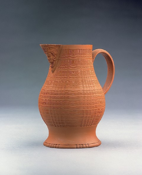
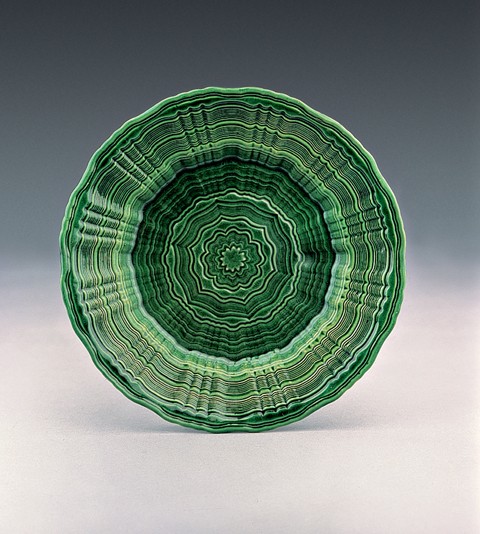
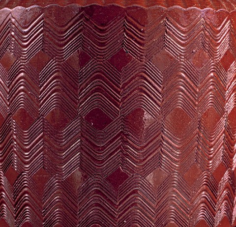
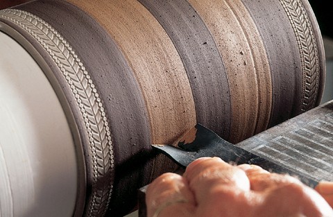
Sometime prior to 1770 a complicated machine known as the engine-turning lathe began to be used to produce surface decorations on earthenware and stoneware in England. By cutting shallow regular patterns into the leather-hard surface of pots as they rotated slowly on this machine, turners in the potteries embellished wares with remarkable precision. This ingenious machine produced extraordinary, geometrically exact flutes and ribs as well as graphically exciting patterns visible through the play of light or by the contrast of colored slips.

We can attribute the development of engine-turned earthenwares and stonewares to Josiah Wedgwood based on surviving letters he sent to his friend and eventual partner, Thomas Bentley. Wedgwood was fascinated by the engine-turning lathe he had seen at Matthew Boulton’s Soho metal-working facility in Birmingham in 1763. He was intrigued by the possibilities that such a machine might hold for use on pottery.[1] In a letter to John Wedgwood dated July 6, 1765, Josiah Wedgwood wrote that “I shall be very proud of the honour of sending a box of pattns to the Queen, amongst which I intend sending two setts of Vases, Creamcolour engine turn’d, & printed.”[2]

Recently, evidence has been published of the even earlier use of an engine-turning lathe on porcelain in London at the Chelsea factory.[3] The Chelsea objects under discussion were probably press-molded using molds created by incorporating engine-turned segments in the original master model, rather than by the process described in this paper. The lathe used for creating those components was significantly different from the lathe described here and was not designed for ceramic production. The possibility remains that another potter (or potters) was involved in similar explorations before or even during Wedgwood’s experiments. If there are any written notations, letters, or other documents regarding those explorations, they have not come to light.

The engine-turning lathe used with wood and metal differs in its construction and operation from the lathe adapted for ceramic use under Wedgwood’s direction. Simple turning lathes had been used for the production of pottery since the early 1700s. By the 1730s virtually all hollow wares (mugs, jugs, cups, bowls, and so forth) were being lathe-turned to shape and thin the bodies. The engine-turning lathe further provided the ability to cut regular patterns in the clay bodies to create decorative elements. 

City directories for the Staffordshire potteries district of the five towns (now known as Stoke-on-Trent) in the late eighteenth and early nineteenth centuries list numerous lathe makers; however, no individuals are identified as engine lathe makers. We look to Wedgwood’s surviving daybooks and correspondence for a hint of the name of the man who first constructed or adapted an engine-turning lathe that met with Wedgwood’s approval.

The history of the use of engine-turning lathes in the ceramic industry during this period is complicated by the rise in popularity of engine turning as a gentleman’s hobby. A company developed by the Holtzapffel family in late-eighteenth-century London manufactured and sold engine-turning lathes for use by people of means who turned ivory and wood into intricate objects having no particular function other than amusement. The Holtzapffel firm maintained a registry of its lathes, recording the names of purchasers and the dates of their transactions. 

In an unpublished history of the company Warren Greene Ogden Jr. lists a number of tantalizing customer names, but unfortunately none has anything to do with the ceramics industry. For example: “Mr. Baddeley bought Number 645 on March 6, 1809,” and on November 9, 1810, a Thomas Wedgwood is listed as purchasing “Number 792, a 5 screw mandrel.” While these are names familiar to students of the Staffordshire pottery industry, in neither case were the customers involved in the manufacture of pottery.[4]

In 1878 the ceramic historian Llewellynn Jewitt wrote of a lathe maker named William Baddeley: 

About 1720 William Baddeley (an old name in the district) commenced making brown ware at Eastwood, Hanley [Staffordshire]. About 1740, having invented an engine-lathe, he began to make turned articles in cane and brown ware. He was succeeded in the pottery by his son William Baddeley, his other son, John Baddeley, taking the business of lathe-making, by which he acquired a competancy [sic], and died in 1841, aged 85. This second William Baddeley made many improvements in the ware and attempted both by an imitation of the body of his vitreous wares and by his mark, to palm off some of his goods as Wedgwood’s. His mark was the word “eastwood” impressed on the ware, but he contrived always to have east indistinct and wood clear; thus hoping to catch the unwary by the latter syllable. He died at an advanced age, and the works at Eastwood, having been sold, his son William Baddeley commenced on Queen Street, Hanley, for the manufacture of terra cotta articles, and a large trade was carried on in earthenware knobs for tin and japanned tea and coffee pots.[5]

Warren Ogden apparently had read these words and concluded thus: “It appears that an Eastwood potter by the name of William Baddeley was the person responsible for introducing engine turning to the Staffordshire potters. Apparently John Baddeley was the individual who first equipped the firm of Josiah Wedgwood for Rose Engine work.”[6]

No city directories for the potteries district are known prior to 1781. Several subsequent directories list lathe makers and the Baddeley name is amongst them. Allbuts Directory for the year 1800, for example, lists:

Samuel Allen, machine-maker, Burslem
Thomas Ball, lathe-maker, Burslem
John Baddeley, lathe-maker, Fields, Hanley
William Lees, lathe-maker and white-smith, Lane End[7]

The normally reliable Mr. Jewitt, by the use of one word, has most likely further confused researchers looking for the origin of engine turning in the Staffordshire potteries. By employing the term “engine-lathe,” Jewitt suggests a very early date of 1740 for the introduction of this machine.[8] It is more likely, however, that the “engine-lathe” he refers to is what we now know as a simple turning lathe. Archaeological findings at the Shelton Farm site of John Astbury confirm that turning lathes were in general use prior to the middle of the eighteenth century, yet no evidence, archaeological or otherwise, suggests the use of engine turning in the Staffordshire potteries prior to the late 1760s.[9]

Perhaps more to the point is the following, published in 1829 by Simeon Shaw:

About 1765, Thomas Greatbatch, turner, at Mr. Palmer’s, Hanley, suggested the movements which form the Engine Lathe, to the noted lathe maker, Mr. John Baddeley, of Eastwood; and worked upon it some years afterwards. Mr. Wedgwood offered eighty guineas each for six, provided Mr. B. would not sell any under that price to other persons. This was not accepted; Charles Chatterly had two made, on one of which were turned several ornamental vases, &c. given to the author by his father-in-law, after he had carefully preserved them more than forty years. Mr. W. engaged Mr. Cox, of Birmingham, to make his; and on the first of his productions, worked old James Bourne, at the Bell Works, about 1766; at any rate, before the commencement of erecting the present Etruria.[10]

The Mr. Palmer referred to is presumed to be the potter Humphrey Palmer of the Church Works, Hanley.

Referring to Wedgwood’s own notations, we find that his initial trials, working with a man named John Taylor, a machine-maker from Birmingham, began in 1763.[11] These first attempts were based on the engravings in a French book published in 1701, L’art de tourner by Plumier.[12] The Plumier-based lathe proved to have both limitations and liabilities. It utilized a two-edged, small-diameter barrel cam combining the features of what the two cams of Wedgwood’s later lathe offered. This made it much too difficult to function in ways that were necessary for ceramic production, primarily in that changing patterns other than the small number of patterns on the barrel required the virtual dismantling of the machine. Wedgwood deserves credit for what is essentially a reinvention of Plumier’s original design to facilitate the production of ceramics.

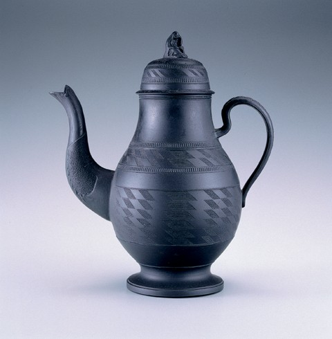
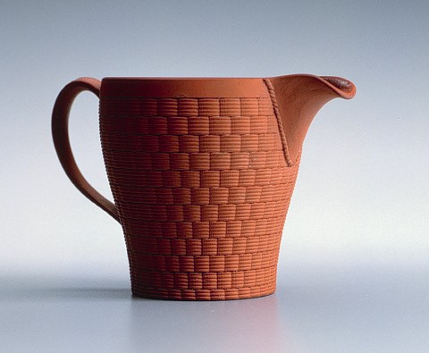
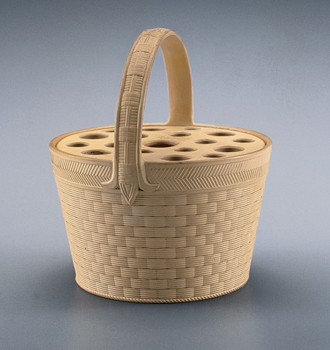
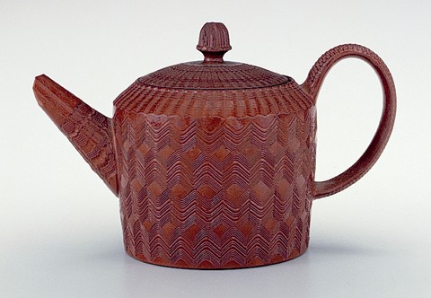
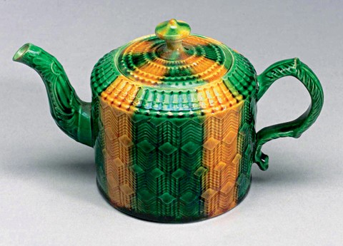
Wedgwood’s most obvious engine-turned products are his jasperwares, but he applied this new technology to his creamwares, canewares, basalts, and red stonewares, too. Based on further correspondence to Bentley, we can infer that real production of his engine-turned wares began about 1767.[13] Following his lead, other potters within the district began similar production shortly thereafter, and in an amazingly short time potters as far away as Bovey Tracey in Devonshire followed suit, probably acquiring machinery from makers in Staffordshire.

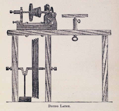
The reference by Warren Ogden to “Rose Engine work” cited previously requires explanation. The type of engine-turning lathe developed and used by Wedgwood is known as a “rose and crown lathe.” The rose refers to the edge cam and the crown to the end cam. It is likely that most engine lathes were made with only the edge cam (also known as a dicing lathe), whereas the larger, more successful potteries employed the more expensive and more complicated rose and crown version.[14]

With all three remaining engine-turning lathes residing in the Wedgwood Museum in Barlaston, one being nineteenth-century and the others twentieth-century copies, it became a matter of conjecture as to just how the original machine worked. Years of speculation made matters more confusing. The only way to understand fully the operation and details of the engine-turning lathe was to build one.

It turns out that two working potters on opposite sides of the Atlantic were at the same point of discovery, each having begun the process of reinvention. Nicholas Mosse of Bennettsbridge, Kilkenny, Ireland, and Donald Carpentier of Eastfield Village, near Albany, New York, had reached similar points in development when they first met in New York City in January 2000. Considerable discussion ensued, with both of the men sharing their hard-won knowledge.

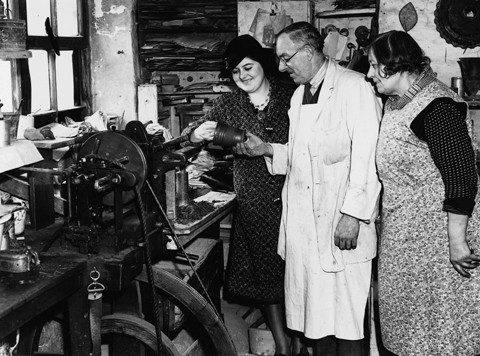
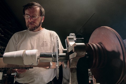
The following explanation of the processes involved is based on the Carpentier lathe. Whereas the eighteenth-century examples were powered by children or women working foot treadles, this lathe runs on electricity. The cutting tools employed on the original machines were handheld or clamped in place; here they are alternately handheld or magnetically held in place. Since Carpentier’s lathe is used to produce pottery for sale, it uses some modern technology to speed production. However, it still closely parallels the original as its function is essentially the same as its eighteenth-century forebears.

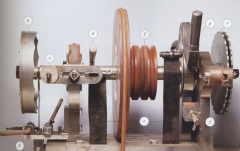
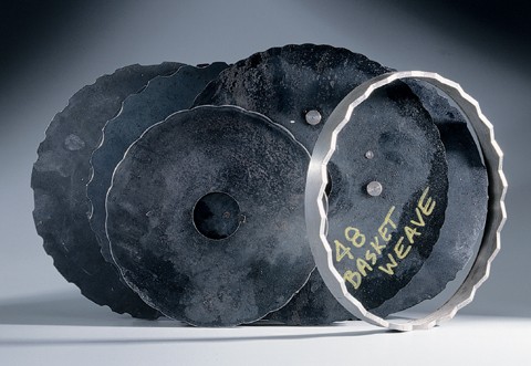
The newly constructed engine-turning lathe uses a steel frame to support a central axle on which can be mounted the crown cam (also known as the end cam), the rose cam (or edge cam), and the chum or mandrel (the plaster or wooden devices to which the pot is affixed). Chums must be custom designed for various forms and sizes of pots. The roses and crowns are also designed to produce different patterns. 

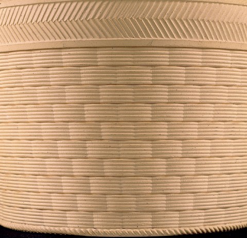
In a typical factory setting, as many as fifty types of these three components could have been used. Patterns may have been further varied by employing various cutting blades, each producing a new pattern when combined with different cams. Another example of the flexibility of the machine involves the placement of the pulley, or tudicle (Wedgwood’s term); when the pulley is in one position, reeding is produced, but when it is reversed, fluting results. Attempts at using both cams simultaneously proved unsuccessful, however, which Wedgwood’s own experiments apparently confirmed. 

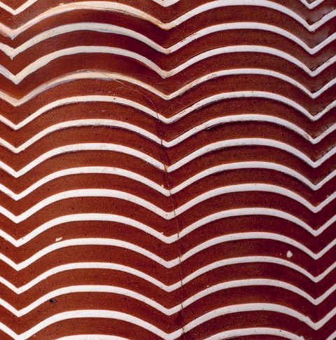
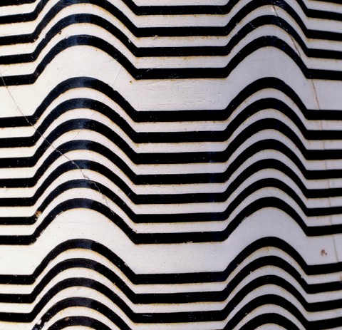
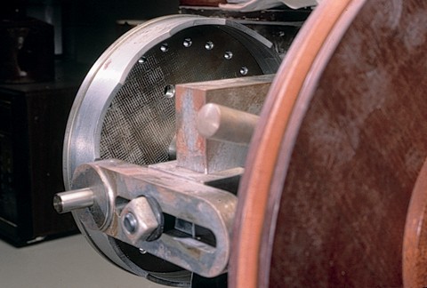
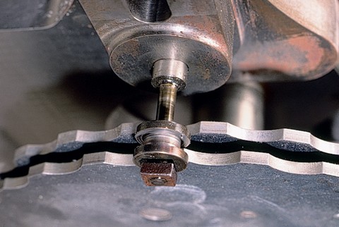
Adjacent to the placement of the mandrel is the rest on which is mounted the cutting blade. The axle has the capacity to move a short distance from end to end (pumping action) when the crown cam is employed. When this action takes place, the blades cut continuously in a pattern, resulting in an up-and-down appearance, either angled or curved, depending on the design of the crown. 

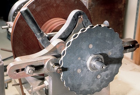
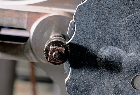
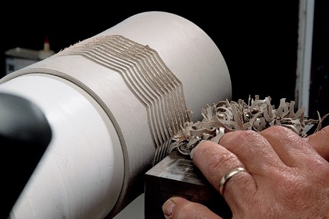
When the rose is employed, the blades cut an intermittent pattern, as the entire frame of the lathe is rocked back and forth by the shape of the rose, the rose being followed by a tudicle or follower, which stays in constant contact with the edge of the cam. As the tudicle follows the edge into a recess, the spring-loaded frame and its mounted vessel rock into contact with the blades, causing the blades to dig into the surface of the clay body, and, as the follower rises onto a high point, it pushes the pot away from the cutting blades. 

There are two devices built into the design that function as locking clamps, preventing either of the two movements. When the rose is employed, the crown clamp is locked to prevent the end-to-end movement of the axle. When the crown is employed, the main locking arm clamp is engaged to prevent the frame from rocking. Both clamps act in opposition to powerful forged steel springs. The axle’s rotation is controlled by an electric motor running leather belts connected to a broad wooden flywheel. The entire lathe is bolted to a countertop work surface. In rose action practice, the axle rotates at a slow speed, with the unit making a regular clicking noise while it rocks back and forth against the cams as the pot is making and breaking contact with the blades. 

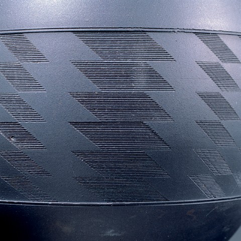
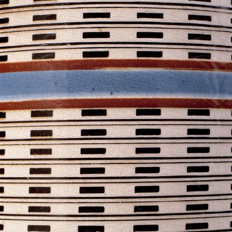
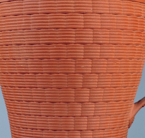
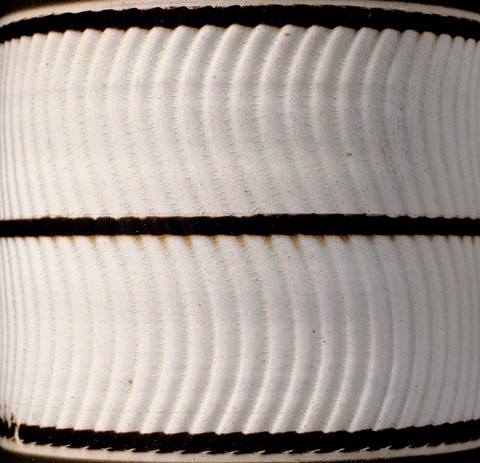
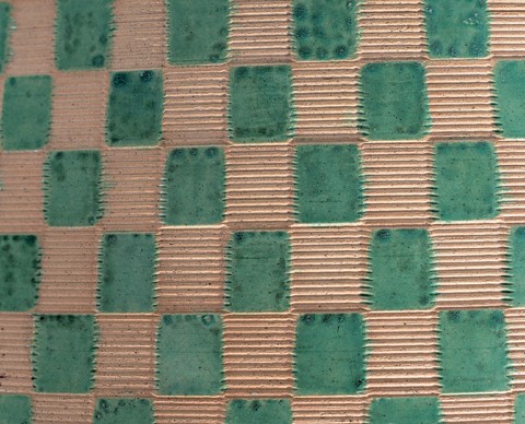
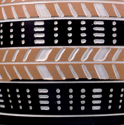
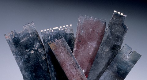
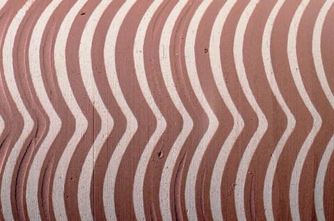
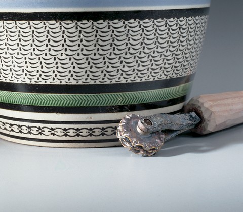
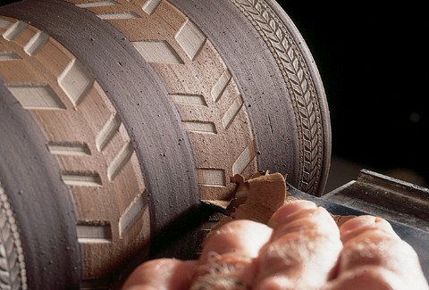
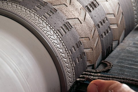
The blades are also custom-made for each pattern and size desired. In general design some are similar to a comb with, for example, six identical, regularly spaced teeth that do the cutting. The patterns produced rely on a play of light and shade for appearance but also have tactile properties. 

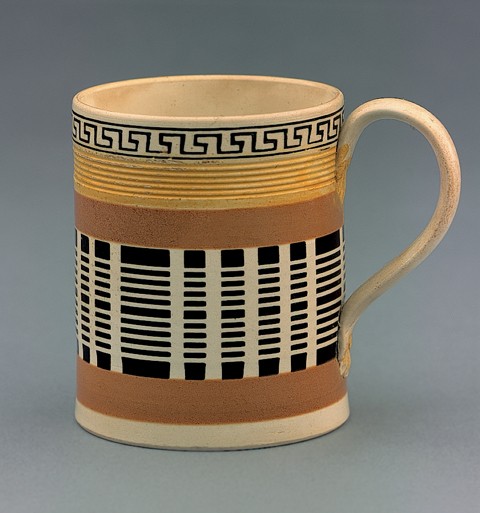
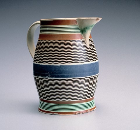
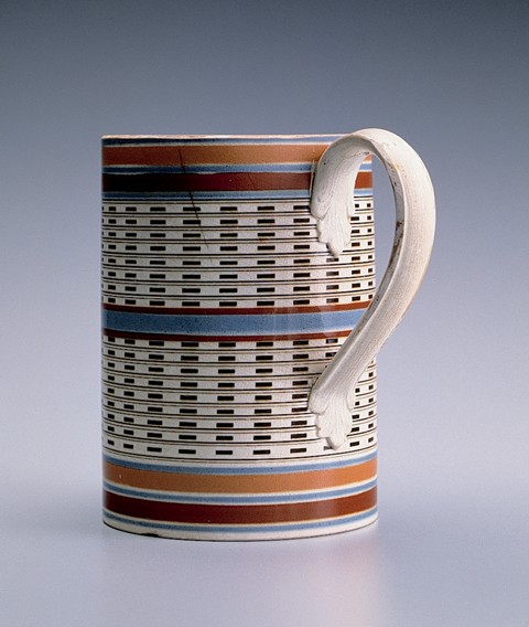
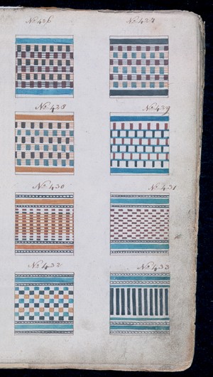
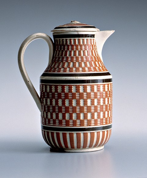
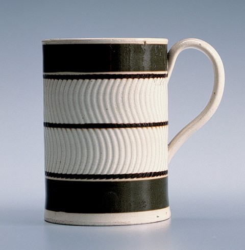
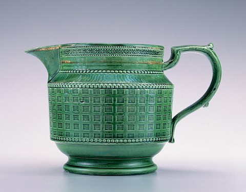
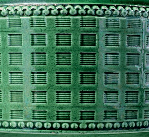
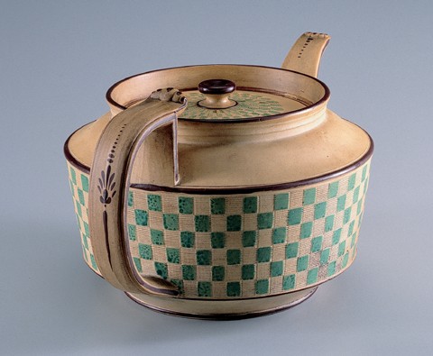
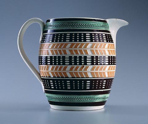
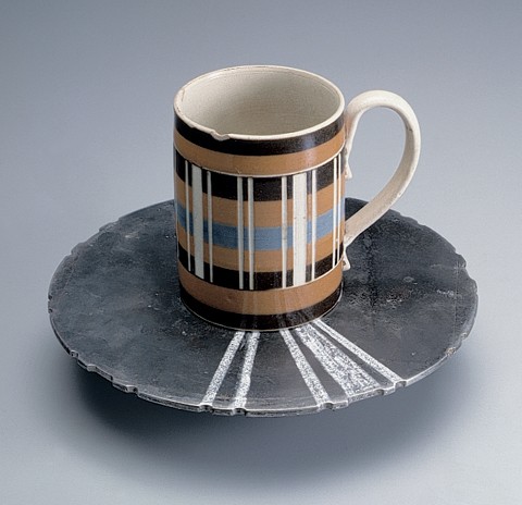
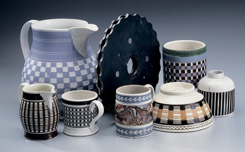
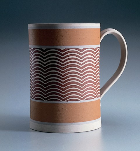
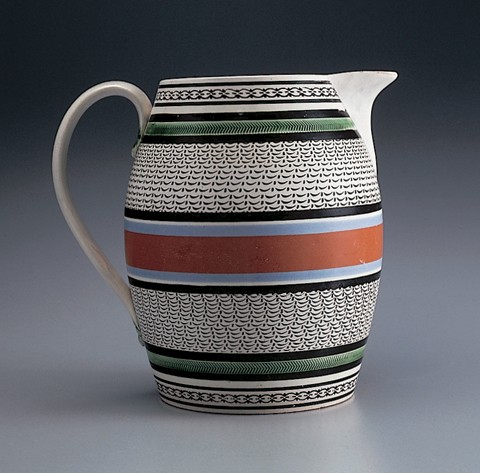
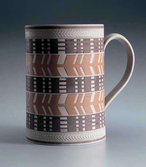
In the case of dipped wares, where contrasting color patterns result, the appearance is greatly enhanced. Wedgwood and a number of his competitors produced colorful geometric patterns on jasperware while, at a generally lower price level, many potteries throughout Great Britain produced engine-turned, slip-decorated utilitarian earthenwares. These products consisted of mugs, jugs, bowls and other functional tablewares with colors and geometric patterns that have a very modern appearance. 

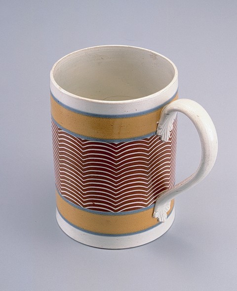
Unlike standard dipped or mocha wares, engine-turned items require a great amount of planning.[15] Potters were not able to just throw a random shape on the potter’s wheel and then turn and decorate it on the engine lathe. The potter would have to carefully draw out and plan the size of each curve, cut, and type of ornament. Knives would be cut to fit the exact shape of large sections of the body in order to produce vertical fluting or reeding. The time needed to set up the lathe for each specific operation was considerable, and therefore economy dictated that large numbers of a specific design be made while the lathe was set up.

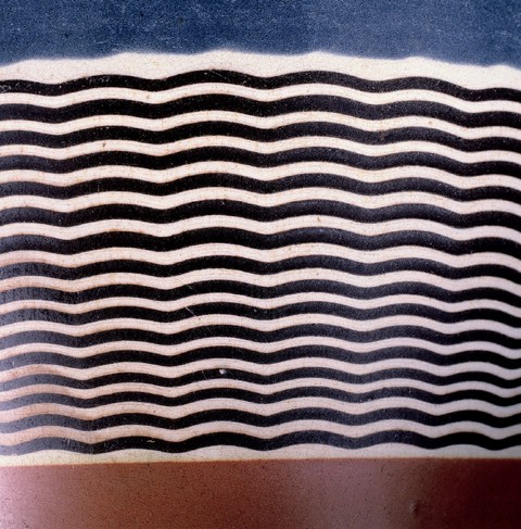
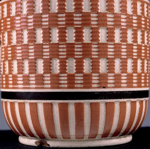
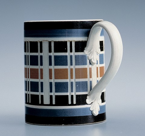
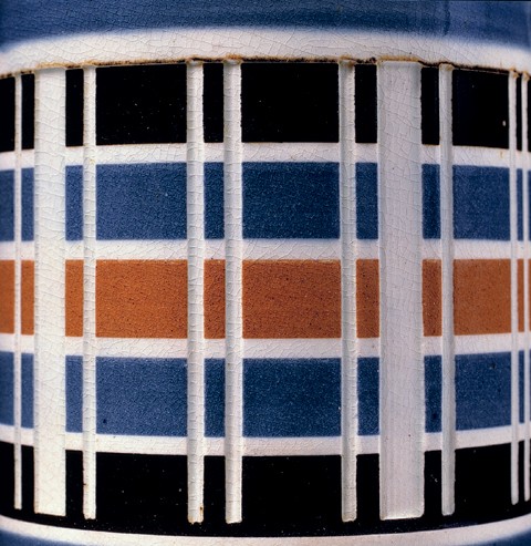
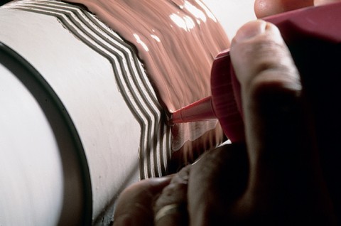
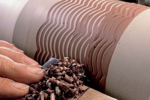
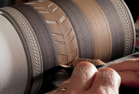
Two basic methods of decoration were employed in producing engine-turned dipped wares. In one, the geometric pattern was cut into the surface of the vessel, which was then dipped or flooded with slip. After the slip had been sufficiently absorbed into the pot body, the excess slip was turned away, leaving the slip remaining only in the created recesses. The other method involved cutting the pattern through a slip coating to reveal the body color in a mechanized version of sgraffito. Layering colors of slip and cutting through one or two layers—rather than through to the body itself—to reveal contrasting colors created more ambitious designs.

The most enduring application of the engine-turning lathe in potteries seems to have been with dipped wares. The more complicated patterns began to fall out of use around 1830, while simple checkered designs may be found on pots made at the very end of the nineteenth century, suggesting continuous production use of this machine at some potteries for more than a century. One late-nineteenth-century pottery making these wares in particular was at Llannelli in Wales. The popularity of these wares is attested to by the later imitations by French and German factories, with existing examples bearing the mark of Villeroy and Boch, Dresden.

[1]

Robin Reilly, Wedgwood (London: MacMillan London, 1989), 1: 201.

[2]

Katherine Eufemia, Lady Farrer, ed., Wedgwood’s Letters to Bentley 1762–1770 (London: Women’s Printing Society, Limited [for private circulation], 1903), p. 47.

[3]

J.V.G. Mallet, “Engine-turning on Chelsea Porcelain, with Considerations on Its Previous Use at Meissen and Vincennes/Sèvres,” English Ceramic Circle Transactions 17, pt. 3 (2001): 420–29. It is possible that those objects considered to have been engine-turned were pressed into a patterned mold. Segments of the block from which the plaster mold was cast conceivably were cut on a straight-line engine lathe commonly used in the metal-working trades. Salt-glazed stonewares of the same period appear to have been produced this way, as the process of engine-turning in the round could not have been used on the marley with raised rims.

[4]

Warren Greene Ogden Jr., “The Pedigree of Holtzapffel Lathes” (manuscript, North Andover, Mass., 1971).

[5]

Llewellynn Jewitt, The Ceramic Art of Great Britain from Pre-historic Times down to the Present Day . . .(London: Virtue and Company, 1878), 2: 401–2.

[6]

Ogden, “Pedigree of Holtzapffel Lathes.”

[7]

Allbut’s Directory, Containing an Alphabetical List of Manufacturers in the Staffordshire Potteries (Stoke-on-Trent, 1800). 

[8]

Jewitt, Ceramic Art of Great Britain, pp. 401–2.

[9]

Sherds from an excavation at the Shelton Farm site headed by David Barker are in the archaeological stores of the Potteries Museum, Hanley, Stoke-on-Trent. See David Barker, “‘The Usual Classes of Useful Articles’: Staffordshire Ceramics Reconsidered,” Ceramics in America, edited by Robert Hunter (Hanover, N.H.: University of New England Press for the Chipstone Foundation, 2001): 84.

[10]

Simeon Shaw, History of the Staffordshire Potteries (Hanley: Printed for the author by G. Jackson, 1829; reprint, New York: Praeger Publishers, 1970), p. 183.

[11]

Farrer, Wedgwood’s Letters, pp. 142–43, “London, May 23, 1767,” referring to Matthew Boulton: “He is I believe the first—or most complete manufacturer in England, in metal. He is very ingenious, Philosophical, & Agreeable. You must be acquainted with him, he has promised to come to Burslem, & wod. attend our congress (we are to have one immediately on my return remember on many accts.) but this year he is too much immers’d in business to indulge he says in anything else. There is a vast difference betwixt the spirit of this Man & the Great Taylor, though both of them have behaved exceeding liberally to me in offering me every improvement they could furnish me with.” Taylor is identified here as a Birmingham manufacturer of buttons, buckles, etc. Preceding this passage is a note referring to Wedgwood’s having seen an ingenious lathe at Boulton’s Soho factory.

[12]

Charles Plumier, L’art de tourner, ou de faire en perfection toutes sortes d’ouvrages au tour, 2d ed., expanded by Charles-Antoine Jombert (Lyons: J. Carte, 1701; Paris: C.-A. Jombert, 1749). See also Farrer, Wedgwood’s Letters, p. 113, February 1767: “We shall want the book on Engine turning with us . . .”; and R[ichard] B[entley], Thomas Bentley, 1730–1780, of Liverpool, Etruria, and London (Guildford: Billing and Sons, 1927; reprint, New York: Wedgwood Society of New York, 1975), p. 56. 

[13]

Farrer, Wedgwood’s Letters, p. 177, between October 12 and 24, 1767: “Inclos’d are Engine Turning, Antiquitys, Plans &c, & first, Engine Turning. I think you will meet with nothing very curious ’till you come to part the third, but I suppose you will skim the other part over. I hope you will read with a pen in your hand, & some sheets of blotting paper before you to enter the memorandms, as they occur to you & let me have the Identical sheets on which such memorandms are made. You will readily conceive which of the Machines may, or may not be applicable to a Potter . . .”; p. 203, Burslem, February 22, 1768: “We have an ingenious & indefatigable smith amongst us, who has ever since Engine Lathes were first introduc’d here, been constantly employd in that business, & he promises me very faithfully that whatever improvements I may instruct him in, he will make them for no one else . . .”; p. 222, Burslem, July 14, 1768: “I have accidentally met with another Artist who is like enough to stick by me if you can send me a good sober honest account of him. He is a Mathematical instrument maker, a Wooden-leg maker, a Caster of Printers types, & in short a Jack of all trades. His name is Brown & he wears a wooden leg, at present he is making me some legs, [Wedgwood was an amputee] but as he can forge Iron and file extremely well, & cast in various metals, I shod. employ him in making & repairing Engine Lathes, punches, & tools of all sorts”; p. 266, by July 1769: “You both want Vases,—you both want flowerpots, and you both want Engin’d ware of various kinds, & we have but two turners & an half for both our works, & for all these things which would employ six or eight.”
 

[14]

One illustrated example (see fig. 52) indicates that some potteries manufactured items that appeared to be engine turned but were not. Instead, it appears that block-makers used an engine-turning lathe to create geometric patterns on the block from which molds were made and sold to factories that did not have an engine lathe.

[15]

See Donald Carpentier and Jonathan Rickard, “Slip Decoration in the Age of Industrialization,” in Ceramics in America, edited by Robert Hunter (Hanover, N.H.: University of New England Press for the Chipstone Foundation, 2001): 115–34.

Ceramics in America 2004

Show all Figures only
Contents


  • [1]

    Robin Reilly, Wedgwood (London: MacMillan London, 1989), 1: 201.

  • [2]

    Katherine Eufemia, Lady Farrer, ed., Wedgwood’s Letters to Bentley 1762–1770 (London: Women’s Printing Society, Limited [for private circulation], 1903), p. 47.

  • [3]

    J.V.G. Mallet, “Engine-turning on Chelsea Porcelain, with Considerations on Its Previous Use at Meissen and Vincennes/Sèvres,” English Ceramic Circle Transactions 17, pt. 3 (2001): 420–29. It is possible that those objects considered to have been engine-turned were pressed into a patterned mold. Segments of the block from which the plaster mold was cast conceivably were cut on a straight-line engine lathe commonly used in the metal-working trades. Salt-glazed stonewares of the same period appear to have been produced this way, as the process of engine-turning in the round could not have been used on the marley with raised rims.

  • [4]

    Warren Greene Ogden Jr., “The Pedigree of Holtzapffel Lathes” (manuscript, North Andover, Mass., 1971).

  • [5]

    Llewellynn Jewitt, The Ceramic Art of Great Britain from Pre-historic Times down to the Present Day . . .(London: Virtue and Company, 1878), 2: 401–2.

  • [6]

    Ogden, “Pedigree of Holtzapffel Lathes.”

  • [7]

    Allbut’s Directory, Containing an Alphabetical List of Manufacturers in the Staffordshire Potteries (Stoke-on-Trent, 1800). 

  • [8]

    Jewitt, Ceramic Art of Great Britain, pp. 401–2.

  • [9]

    Sherds from an excavation at the Shelton Farm site headed by David Barker are in the archaeological stores of the Potteries Museum, Hanley, Stoke-on-Trent. See David Barker, “‘The Usual Classes of Useful Articles’: Staffordshire Ceramics Reconsidered,” Ceramics in America, edited by Robert Hunter (Hanover, N.H.: University of New England Press for the Chipstone Foundation, 2001): 84.

  • [10]

    Simeon Shaw, History of the Staffordshire Potteries (Hanley: Printed for the author by G. Jackson, 1829; reprint, New York: Praeger Publishers, 1970), p. 183.

  • [11]

    Farrer, Wedgwood’s Letters, pp. 142–43, “London, May 23, 1767,” referring to Matthew Boulton: “He is I believe the first—or most complete manufacturer in England, in metal. He is very ingenious, Philosophical, & Agreeable. You must be acquainted with him, he has promised to come to Burslem, & wod. attend our congress (we are to have one immediately on my return remember on many accts.) but this year he is too much immers’d in business to indulge he says in anything else. There is a vast difference betwixt the spirit of this Man & the Great Taylor, though both of them have behaved exceeding liberally to me in offering me every improvement they could furnish me with.” Taylor is identified here as a Birmingham manufacturer of buttons, buckles, etc. Preceding this passage is a note referring to Wedgwood’s having seen an ingenious lathe at Boulton’s Soho factory.

  • [12]

    Charles Plumier, L’art de tourner, ou de faire en perfection toutes sortes d’ouvrages au tour, 2d ed., expanded by Charles-Antoine Jombert (Lyons: J. Carte, 1701; Paris: C.-A. Jombert, 1749). See also Farrer, Wedgwood’s Letters, p. 113, February 1767: “We shall want the book on Engine turning with us . . .”; and R[ichard] B[entley], Thomas Bentley, 1730–1780, of Liverpool, Etruria, and London (Guildford: Billing and Sons, 1927; reprint, New York: Wedgwood Society of New York, 1975), p. 56. 

  • [13]

    Farrer, Wedgwood’s Letters, p. 177, between October 12 and 24, 1767: “Inclos’d are Engine Turning, Antiquitys, Plans &c, & first, Engine Turning. I think you will meet with nothing very curious ’till you come to part the third, but I suppose you will skim the other part over. I hope you will read with a pen in your hand, & some sheets of blotting paper before you to enter the memorandms, as they occur to you & let me have the Identical sheets on which such memorandms are made. You will readily conceive which of the Machines may, or may not be applicable to a Potter . . .”; p. 203, Burslem, February 22, 1768: “We have an ingenious & indefatigable smith amongst us, who has ever since Engine Lathes were first introduc’d here, been constantly employd in that business, & he promises me very faithfully that whatever improvements I may instruct him in, he will make them for no one else . . .”; p. 222, Burslem, July 14, 1768: “I have accidentally met with another Artist who is like enough to stick by me if you can send me a good sober honest account of him. He is a Mathematical instrument maker, a Wooden-leg maker, a Caster of Printers types, & in short a Jack of all trades. His name is Brown & he wears a wooden leg, at present he is making me some legs, [Wedgwood was an amputee] but as he can forge Iron and file extremely well, & cast in various metals, I shod. employ him in making & repairing Engine Lathes, punches, & tools of all sorts”; p. 266, by July 1769: “You both want Vases,—you both want flowerpots, and you both want Engin’d ware of various kinds, & we have but two turners & an half for both our works, & for all these things which would employ six or eight.”
     

  • [14]

    One illustrated example (see fig. 52) indicates that some potteries manufactured items that appeared to be engine turned but were not. Instead, it appears that block-makers used an engine-turning lathe to create geometric patterns on the block from which molds were made and sold to factories that did not have an engine lathe.

  • [15]

    See Donald Carpentier and Jonathan Rickard, “Slip Decoration in the Age of Industrialization,” in Ceramics in America, edited by Robert Hunter (Hanover, N.H.: University of New England Press for the Chipstone Foundation, 2001): 115–34.