


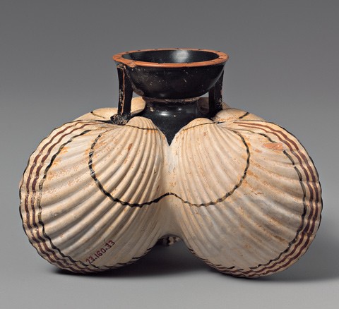
Aryballos, Greek, Attic, late 6th century B.C. Terracotta. H. 2 7/16". (Courtesy, The Metropolitan Museum of Art, New York, Rogers Fund, 1923; image © The Metropolitan Museum of Art.) Molded in the form of three cockle shells, this small bottle held cosmetic oils.

Pitcher, Bernard Palissy and workshop, France, 1556–1590. Earthenware. H. 7 1/2". (Courtesy, Réunion des Musées Nationaux, Musée du Louvre, Paris; photo, J. G. Berizzi/Art Resource, New York.)
Fragment, cast of shells, Bernard Palissy and workshop, France, 1556–1590. Terracotta. L. 16 1/4". (Courtesy, Réunion des Musées Nationaux, Musée de la Renaissance, Écouen, France; photo, R. G. Ojeda/Art Resource, New York.)
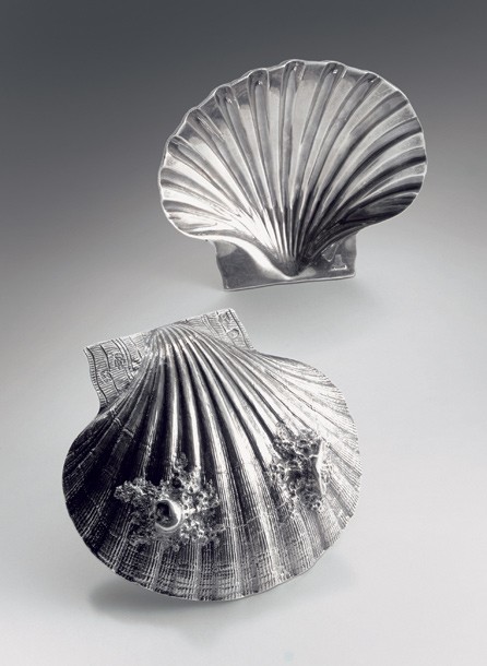
Pair of silver shell dishes,
Paul de Lamerie, London, 1732. W. 5". (Courtesy, Christie’s New York; © 2006 Christie’s Images Ltd.) The realistic nature of these shells suggests they were cast from molds taken directly from a Pecten maximus shell.

Pickle stand, Derby porcelain factory, England, ca. 1765. Soft-paste porcelain. H. 14 1/4". (Colonial Williamsburg Foundation.)
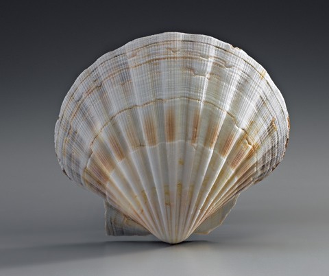
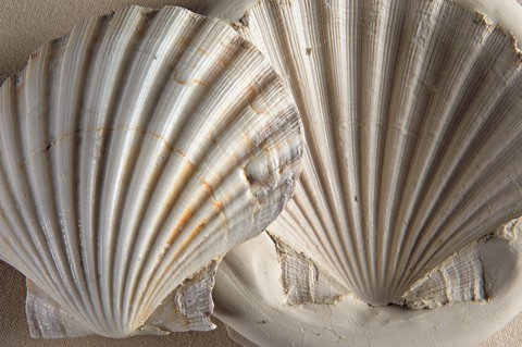
Irish scallop (Pecten maximus). H. 5". This example is the deeply cupped right valve of the scallop. Note the rounded ribs in cross section and the large anterior ears or wings at the hinge.
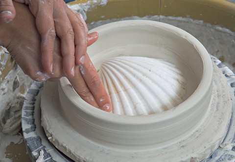
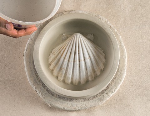
A thick-walled shallow casting vessel is thrown on the wheel. The scallop shell is centered and pushed into the soft clay bottom. A thin coat of oil is applied to the scallop shell as releasing agent to prevent it sticking to the plaster.
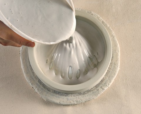
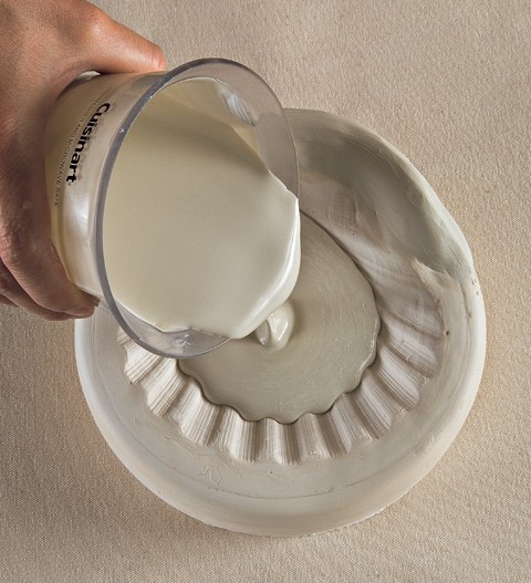
Once the clay wall of the casting vessel has dried to leather hard, a mixture of plaster is slowly poured into the form over the shell, trying to avoid trapping air bubbles, and filled to the top.
Once the clay wall of the casting vessel has dried to leather hard, a mixture of plaster is slowly poured into the form over the shell, trying to avoid trapping air bubbles, and filled to the top.
Once the clay wall of the casting vessel has dried to leather hard, a mixture of plaster is slowly poured into the form over the shell, trying to avoid trapping air bubbles, and filled to the top.
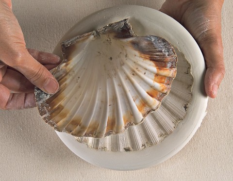
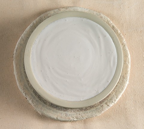
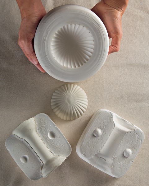
After the plaster cures, the clay walls of the casting vessel are peeled away and the scallop shell is removed from the mold. Once dry, the mold is ready for casting.
After the plaster cures, the clay walls of the casting vessel are peeled away and the scallop shell is removed from the mold. Once dry, the mold is ready for casting.
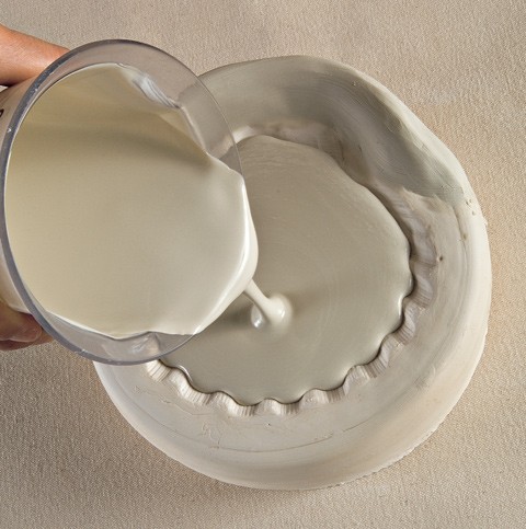
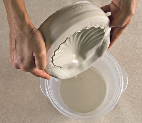
To begin the casting process, the porcelain clay slip is poured into the mold.
To begin the casting process, the porcelain clay slip is poured into the mold.
It is essential that the mold be filled to the edge of the casting. The soft clay wall at the rear of the mold keeps the slip from running out and aids in the “pouring off” of excess slip.

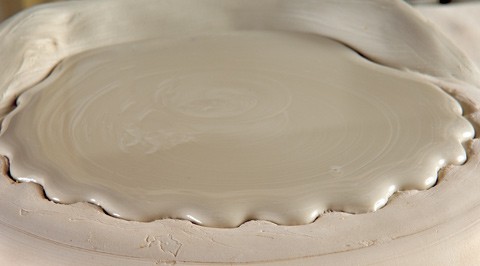
The filled mold is left to stand for several minutes while the plaster body absorbs moisture from the porcelain slip. The thickness of the cast depends on how long the slip remains in the mold before it is carefully poured away.
The filled mold is left to stand for several minutes while the plaster body absorbs moisture from the porcelain slip. The thickness of the cast depends on how long the slip remains in the mold before it is carefully poured away.
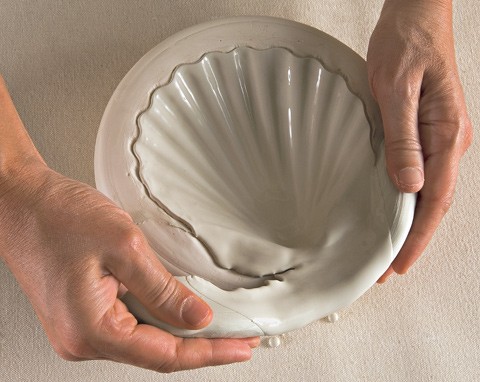
After the cast shell hardens, the soft clay retaining wall is peeled away and the shell is carefully removed from the mold.
After the cast shell hardens, the soft clay retaining wall is peeled away and the shell is carefully removed from the mold.
After the cast shell hardens, the soft clay retaining wall is peeled away and the shell is carefully removed from the mold.
Two other plaster molds were needed to create the remaining major components of the pickle stand. A one-piece mold was used to create the top cup for the stand. A two-piece press mold was used to form the central stalk.
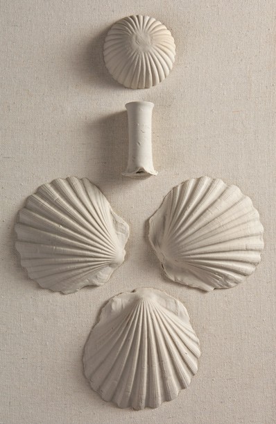
The molded major components of the pickle stand at the leather-hard stage.
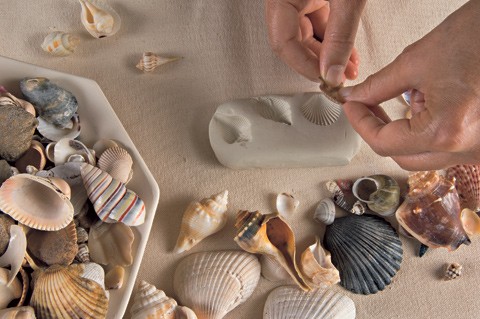
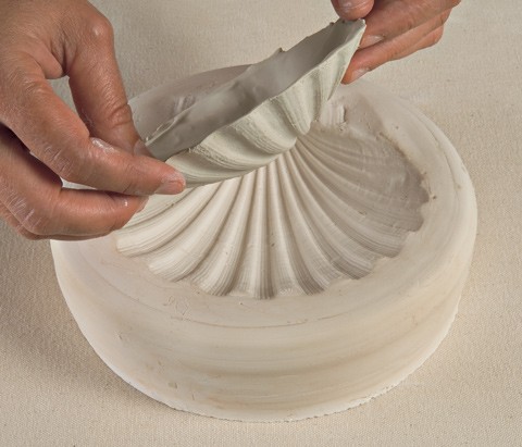
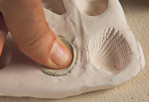
The creation of the various smaller shells, which represent an encrusted marine environment, requires a number of small press molds taken directly from natural shell specimens. (The examples shown here were selected for demonstration purposes and do not necessarily correlate with all the smaller shells used on the original Bonnin and Morris pickle stand.) To create the molds, the shells were carefully pressed into prepared slabs of soft porcelain clay.
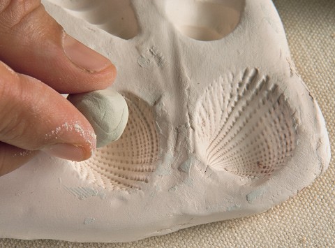
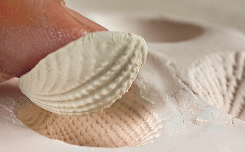
The porcelain slabs were allowed to dry and subsequently fired to bisque temperature. A small ball of porcelain clay was pushed into the molds and extracted to create the necessary clay shells. The porous nature of the bisque porcelain allowed the casts to be removed from the mold right away.
The porcelain slabs were allowed to dry and subsequently fired to bisque temperature. A small ball of porcelain clay was pushed into the molds and extracted to create the necessary clay shells. The porous nature of the bisque porcelain allowed the casts to be removed from the mold right away.
The porcelain slabs were allowed to dry and subsequently fired to bisque temperature. A small ball of porcelain clay was pushed into the molds and extracted to create the necessary clay shells. The porous nature of the bisque porcelain allowed the casts to be removed from the mold right away.
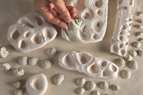
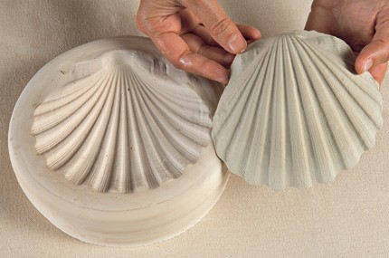
A variety of working molds were necessary to create the repertoire of smaller shells similar to those used on the Bonnin and Morris pickle stand.
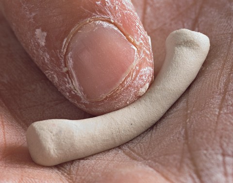
Representations of the small tube worms were hand-modeled as clay coils. The openings were made using a flat metal blade.

Representations of the small tube worms were hand-modeled as clay coils. The openings were made using a flat metal blade.
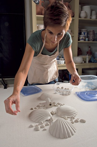
Michelle Erickson laying out the molded components of the pickle stand before assembly.
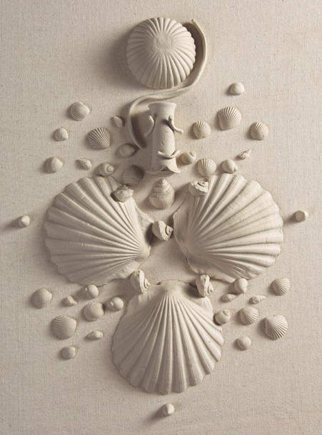
A schematic representation of some of the clay components of the pickle stand. Each of these objects would have to be prepared and ready at the time of the assembly. More than seventy separate elements were required to re-create this object.
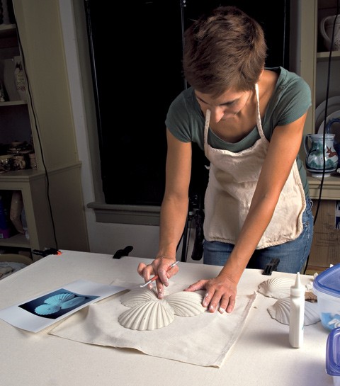
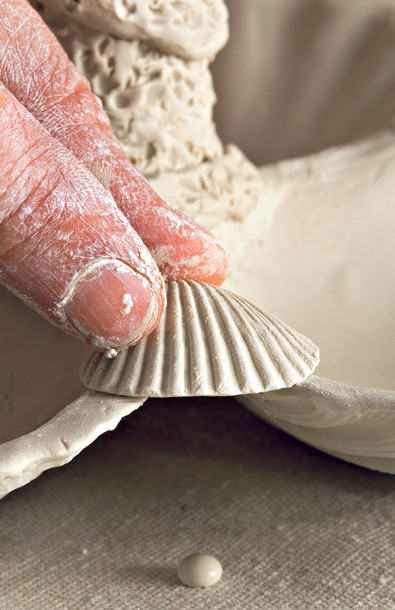
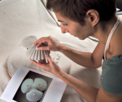
The assembly of the clay components begins with the orientation of the three large scallop shells. The ears of the scallop shells are cut away before they are fitted together to form the base.
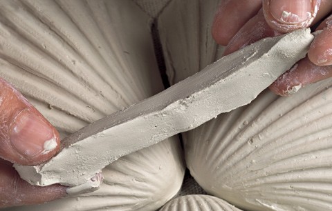
A triangular clay strip acts as a fillet between the shells, providing an integral structural connection. Drops of slip are used to strengthen the adhesion and the strip is worked into the crevices.
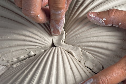
A triangular clay strip acts as a fillet between the shells, providing an integral structural connection. Drops of slip are used to strengthen the adhesion and the strip is worked into the crevices.
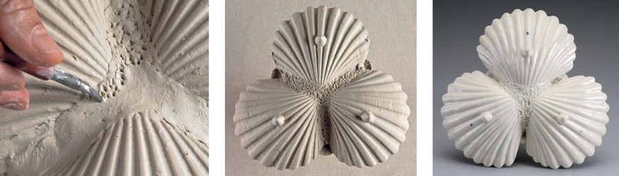
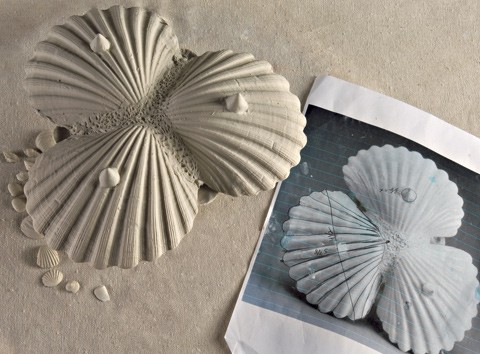
The clay fillets are stippled to simulate fossil coral. The stippling also helps reinforce the structure of the stand. The base from the original is shown at the far right.

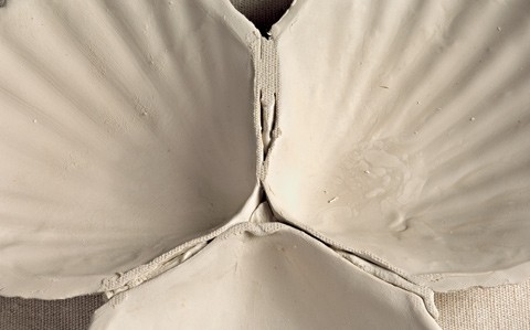
The inside edges of the scallop shells are cleaned with a wet sponge.
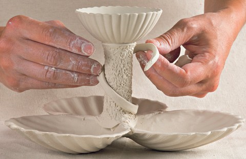
The upper crevices between the scallop shells are filled with small clay strips and stippled. The stalk is now adhered to the center of the scallop shells. Note the flange at the bottom of the stalk, which aids in the attachment. The flanges are hand-worked down over the shells to form a secure bond.
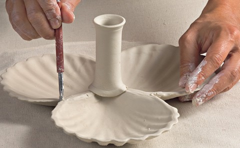
The upper crevices between the scallop shells are filled with small clay strips and stippled. The stalk is now adhered to the center of the scallop shells. Note the flange at the bottom of the stalk, which aids in the attachment. The flanges are hand-worked down over the shells to form a secure bond.
The top cup is joined to the stalk using slip. As with the base fillets, the stalk is stippled to simulate fossilized coral, a sample of which is shown.
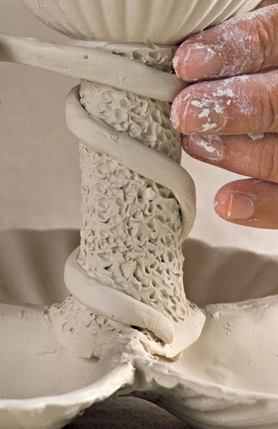
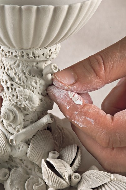
A strand of seaweed is represented by a flattened coil of clay wrapped around the stalk. This device serves to conceal the joins of the stalk at the base of the top cup and provides a point of attachment for the small snail-like shells as they ascend the column.
A strand of seaweed is represented by a flattened coil of clay wrapped around the stalk. This device serves to conceal the joins of the stalk at the base of the top cup and provides a point of attachment for the small snail-like shells as they ascend the column.
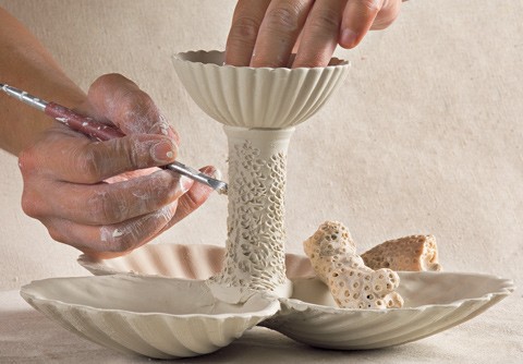
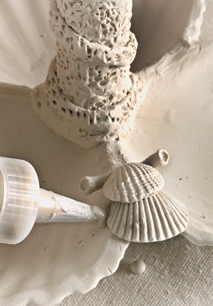
The pickle stand is ready for the attachment of the small shells. Using the originals as a general guide, a group of cockle shells is built up along with a tube worm. Drops of slip are used to help secure these shells.
The pickle stand is ready for the attachment of the small shells. Using the originals as a general guide, a group of cockle shells is built up along with a tube worm. Drops of slip are used to help secure these shells.
The pickle stand is ready for the attachment of the small shells. Using the originals as a general guide, a group of cockle shells is built up along with a tube worm. Drops of slip are used to help secure these shells.
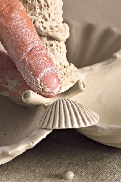
A final cockle shell is placed in position. Note that this shell consists of two separately molded shells that are joined to simulate a live cockle.
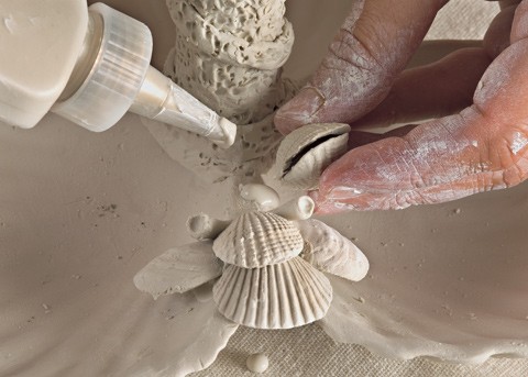
After the three major clusters of cockle shells are arranged, the smaller marine shells and additional tube worms are placed on the stalk.

A needle tool facilitates the delicate placement of the smaller shells.
The final stage in the assembly is the placement of the cone-shaped feet, using a photograph of the original pickle stand base as a guide. The stand has to be turned upside down for this final step.

The final stage in the assembly is the placement of the cone-shaped feet, using a photograph of the original pickle stand base as a guide. The stand has to be turned upside down for this final step.
A view of the base of the assembled pickle stand next to a notated photograph of an original. Note the high definition of the rounded ribs and the presence of the circular growth rings.
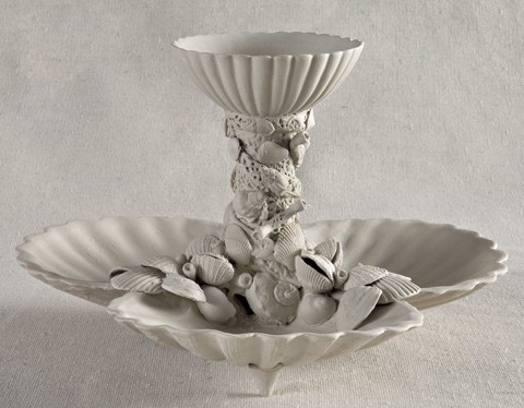
Overall view of the assembled pickle stand in leather-hard state.

A pair of pickle stands in
biscuit and leather-hard states after the Bonnin and Morris originals juxtaposed next to a ca. 1765 Bow porcelain model. The additional stages of the finishing process include a biscuit firing, followed by the application of blue decoration and a final glaze firing. The unfinished stands would lose approximately 15 percent of their size during the two firings.